Day
By day, charging runs at reduced power
The building consumes more → charging power falls.
Dynamic load management for car parks
BMA distributes the building's free power between charging stations in real time — without exceeding the site limit.

Illustrative example. Values are notional.
Where the limit appears
Illustrative example. A specific site is calculated from actual loads and supply parameters.
Counted by nameplate
100 × 7 kW = 700 kW
But cars stand for 8–12 hours and never need 700 kW all at once. What is needed is not a sum of nameplates but management of the available power.
The limit is not created by the charging station but by the free power of the specific building. While there is spare capacity, connection is routine; the refusal goes to whoever asks once the margin is used up.
Solution
Every building has a permitted capacity granted at grid connection. In practice the building almost never uses all of it, and at night it consumes noticeably less. That difference is already connected to the grid — BMA hands it to the charging stations to exactly the extent it is free at that moment.
Day
The building consumes more → charging power falls.
Evening peak
BMA automatically limits the charging load.
Night
The building unloads → charging power rises.
Available charging power = permitted capacity of the site − current building load − technical reserve
Illustrative example. Notional site: permitted capacity 600 kW, technical reserve 40 kW, 40 cars connected, stations up to 7 kW; in “No management” mode a notional fixed cap of 60 kW is shown. Algorithms, measurement frequency and the size of the reserve are defined by the supply architecture of the specific site. This is not a calculation of a real building and not a promise of a specific number of stations or charging speed.
How BMA works
One continuous cycle: it never stops while at least one car is plugged in.
The current building load at the main input — all consumption, per phase, in real time.
The actually free power, taking the technical reserve into account.
The available power between the connected cars — each station gets its own current limit.
The limits at every change of the building load.
The site from exceeding its permitted capacity: stations can only reduce the load, never raise it.
Control is by current: each station is given its own current limit. The station passes that limit to the car over the signalling line in the charging cable and holds it, so the total stays within the budget.
Algorithms, measurement frequency and the size of the reserve are defined by the supply architecture of the specific site.
Architecture
The power balance is calculated locally, in the load controller. The cloud handles metering and monitoring but is not part of the control loop.
BMA charging stations
Cars
The balance and the station setpoints are produced in the cabinet on site. If the cloud link drops, power distribution continues unchanged — only data transfer pauses: session history and accounts update once the link is back.
If a station loses contact with the controller, it falls back to a preset minimum or switches off. So the permitted capacity of the site cannot be exceeded under any scenario. The site limit can also be set externally — from the grid operator's account.
Illustrative example. Values are notional.
One BMA system
The station, the algorithm and the control channel are the responsibility of one BMA system. That is why the guarantee of staying within the limit rests on the architecture, not on settings.
Charging point that holds the permitted current.
Local measurement and calculation of the available power.
Monitoring, metering and digital services.

Scaling
The same system grows with the car park.
1 cabinet · 9 or 15 points
Two versions of the load controller.
Several cabinets
One master module, the rest slaves.
New station groups
Transition by cabinet firmware; the stations at the spaces stay in place.
Large car park
The number of points grows with demand within the available power.
The equipment set, the measurement scheme and the distribution of points across phases are defined by the project after a technical site survey.
Applications
The effect is greatest when a car stays in place for 8–12 hours while the building load is at its lowest.

Daytime parking for staff and tenants within the building's power.
Company and staff vehicles; priorities and limits set by configuration, not by hardware.
Housing, offices and services on one main input: one energy balance for the whole site.
Overnight guest parking. Suitable where spaces are assigned to rooms or the hotel controls access to the point; otherwise the access scenario is designed separately.
Who gets what
More charging points without automatically increasing the site's capacity.
Sees the load and the state of every point.
Charges at their own space with individual metering.
Gets an observable and manageable charging load.
Company
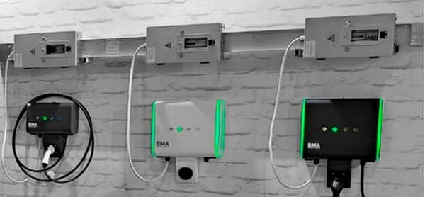
BMA GreenPower is the charging-infrastructure division of the Terra-Tok engineering group: in-house production of electrical equipment and busbar systems.
We develop and manufacture the whole chain ourselves — the charging station, the load controller and the cloud software. It is not an assembly of third-party components and not an add-on to someone else's equipment.
Certificates, technical documentation and a reference list are provided on request.
First step
We will give a preliminary estimate of how many charging points can be placed with dynamic load management and what source data the calculation needs.
What the calculation needs
Email: sales@bma-gp.com Phone: +7 (343) 226-77-40